
UP009N10LT TOLT Package - MOSFETs designed for industrial applications
The demand for MOSFETs in industrial applications is increasing. From mechanical solutions to more demanding application conditions, semiconductor manufacturers are required to develop new packaging solutions and implement technological improvements. From the original surface mount devices (SMDS) such as TO-252, TO the latest pin-free packages and significant improvements in internal silicon technology, MOSFET solutions are evolving to better meet the new requirements of the industrial market. Here, we cover UOE's TOLT package, thermal performance, and board reliability.
Key features, key benefits and applications:
Key features:
* Ultra-Low RDS (on)
* High rated current greater than 300A
* Top heat dissipation
* Negative pin body height difference
* Wuxi cooling pad
Main advantages:
* High system efficiency, extended battery life
* High power density
* Excellent thermal performance, saving heat dissipation system
* Minimize thermal resistance to the heat sink
Important Applications:
* Mobile robot
* Drone
* Light electric vehicle
* Electric loading truck
* Electric bicycle
* Power tools
* Battery management system
Target application market
UOE's TOLT-packaged power MOSFETs help achieve very high power levels. Thanks to improved thermal resistance through top cooling, TOLT can meet the demands of power-demanding applications without increasing the number of devices and the size of the system. Therefore, the key application of TOLT package is high current application. The package is suitable for high power motor drivers with power levels up to 50 kW.
Package design
The concept of the new TOLT package is different from the standard bottom-cooling power MOSFETs. In TOLT, the lead frame in the package is inverted and the drain pad (bottom of chip = drain connection) is exposed at the top of the package.
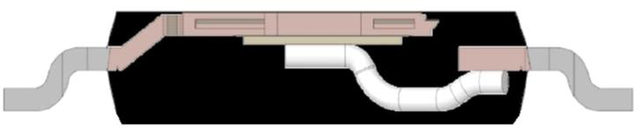
Figure 1 Side view of TOLT
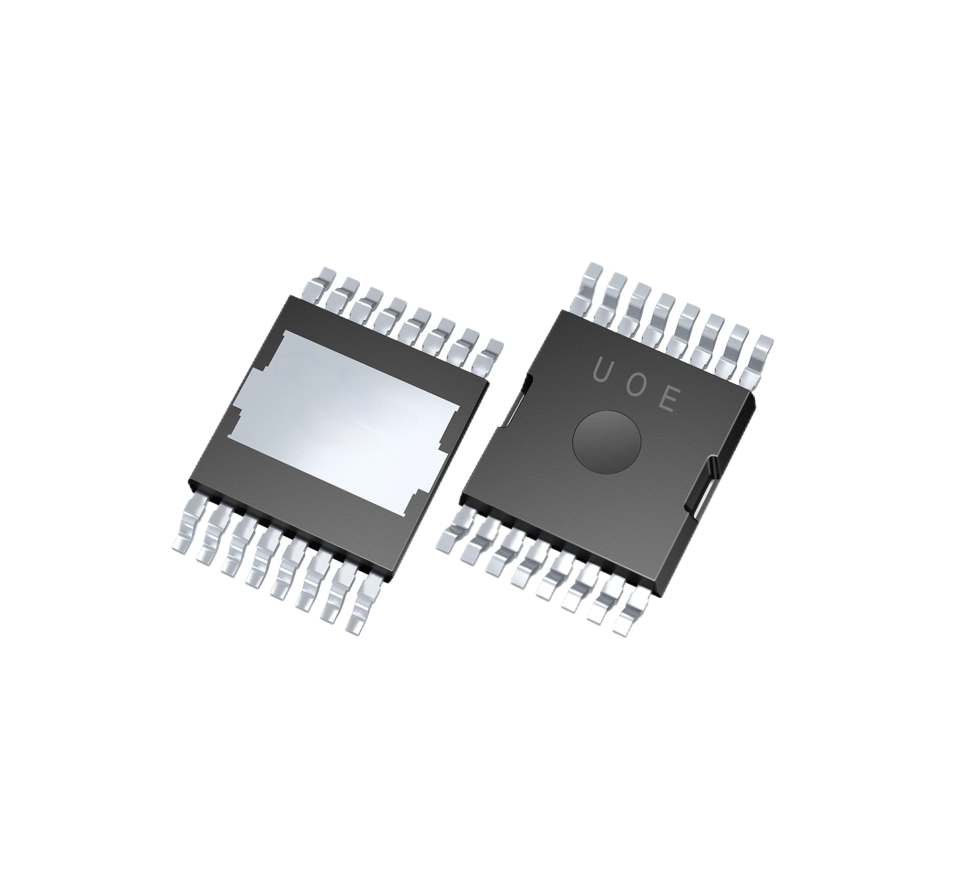
Figure 2 Package appearance
Figures 3 and 4 show the grid, source, and drain pins. A row of eight pins is connected to the bare pad at the top for drain connection to the board. On the other side of the package, one pin is used for gate control and the remaining seven pins are connected to the current source.
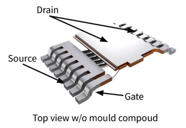
Figure 3 TOLT 3D view
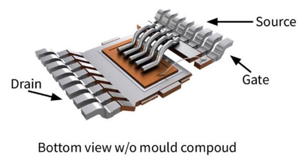
Figure 4 TOLT bottom view
TOLT advantages and principles
1, the top heat dissipation can not only obtain higher application power, but also several other important advantages. In standard heat dissipation schemes (Figure 6), the heat sink is usually installed below the PCB. The heat transfer path from the chip to the outside is as follows: The disadvantage of this solution is reduced thermal performance, depending on the PCB and TIM/ thermal paste parameters. Poor thermal conductivity of these components can lead to overheating and reduced application power, and can also mean higher heat dissipation costs. In addition, the assembly board needs to withstand higher temperatures, which requires the use of more expensive PCBS.

Figure 5 Heat path in the rear heat dissipation mode
2, the SMD component can be placed under the TOLT MOSFET at the bottom of the PCB (Figure 10) to optimize the available area.
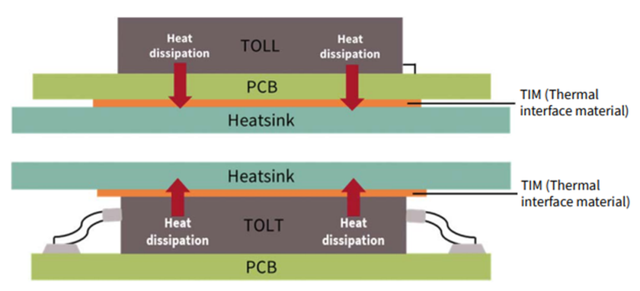
Figure 6 Schematic diagram of TOLL & TOLT heat dissipation
3. TOLT increases current/power processing capacity. Compared with TOLL package, RthJA in TOLT package is reduced by 20%, RthJC is improved by nearly 50%, and Rth(J-heatsink) is reduced by 36%.
4. Extra advantage
In addition to achieving higher power density or cost savings for cooling systems, TOLT products have other advantages. Here are some examples:
Since the heat sink is not installed under the PCB and no heat is transferred to the board through the bottom side of the MOSFET, the gate driver or capacitor can be placed on the other side of the PCB. Such a solution makes more efficient use of PCB space.
● Increase creepage distance (distance between source and drain potential).
● PCBS with lower glass transition temperatures can be used.
● Less heat is transferred to the PCB and nearby components.
5. Thermal interface material thickness
In order to guarantee the best thermal performance of TOLT packages and to ensure the lowest possible thermal resistance of the packages, optimizing the TIM thickness is essential. Below are simulations of several different TIM thicknesses for TOLT packages to analyze their impact on the total RTH from junction to fin. In the simulation, the heat sink temperature is fixed at an ambient temperature of 85°C.
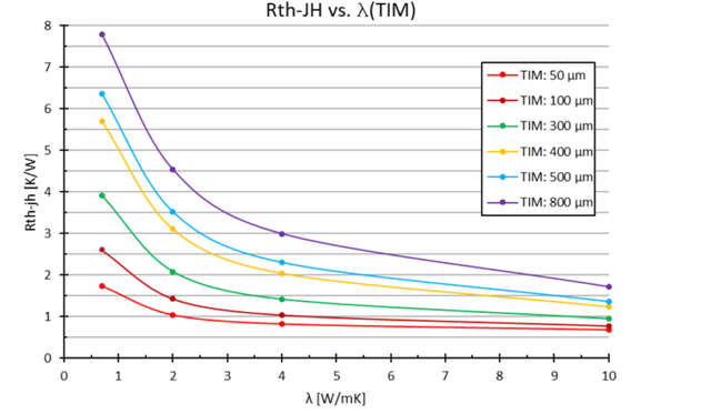
FIG. 7 shows the correlation of Rth with TIM thermal conductivity of different TIM thicknesses
As can be seen from the figure, the thinner the TIM, the lower the thermal resistance. However, attention should be paid to the thermal conductivity (λ) value of TIM. Better thermal conductivity compensates for the negative effects of TIM thickness.
The thermal conductivity of existing TIMs on the market is typically between 3 and 6 W/mK. In order to achieve optimal thermal performance and adequate electrical isolation phase balance, system engineers should optimize the thickness and thermal parameters of the TIM.
The material most commonly used by customers and widely used in the market is TIM with thermal conductivity in the range of 3 to 4 W/mK. According to the simulation of this value, the thermal resistance between the MOSFET junction and the heat sink varies between 0.8 and 3K/W, depending on the TIM thickness. When the actual TIM thickness is 300 to 500 μm, the thermal resistance can reach 1.5 to 2.4K/W. When Rth is equal to 2.4 K/W and the temperature difference between the MOSFET junction and the housing is 90°C (assuming Tcase = 85°C and Tjmax = 175°C), a single TOLT MOSFET can consume about 40 W of power.
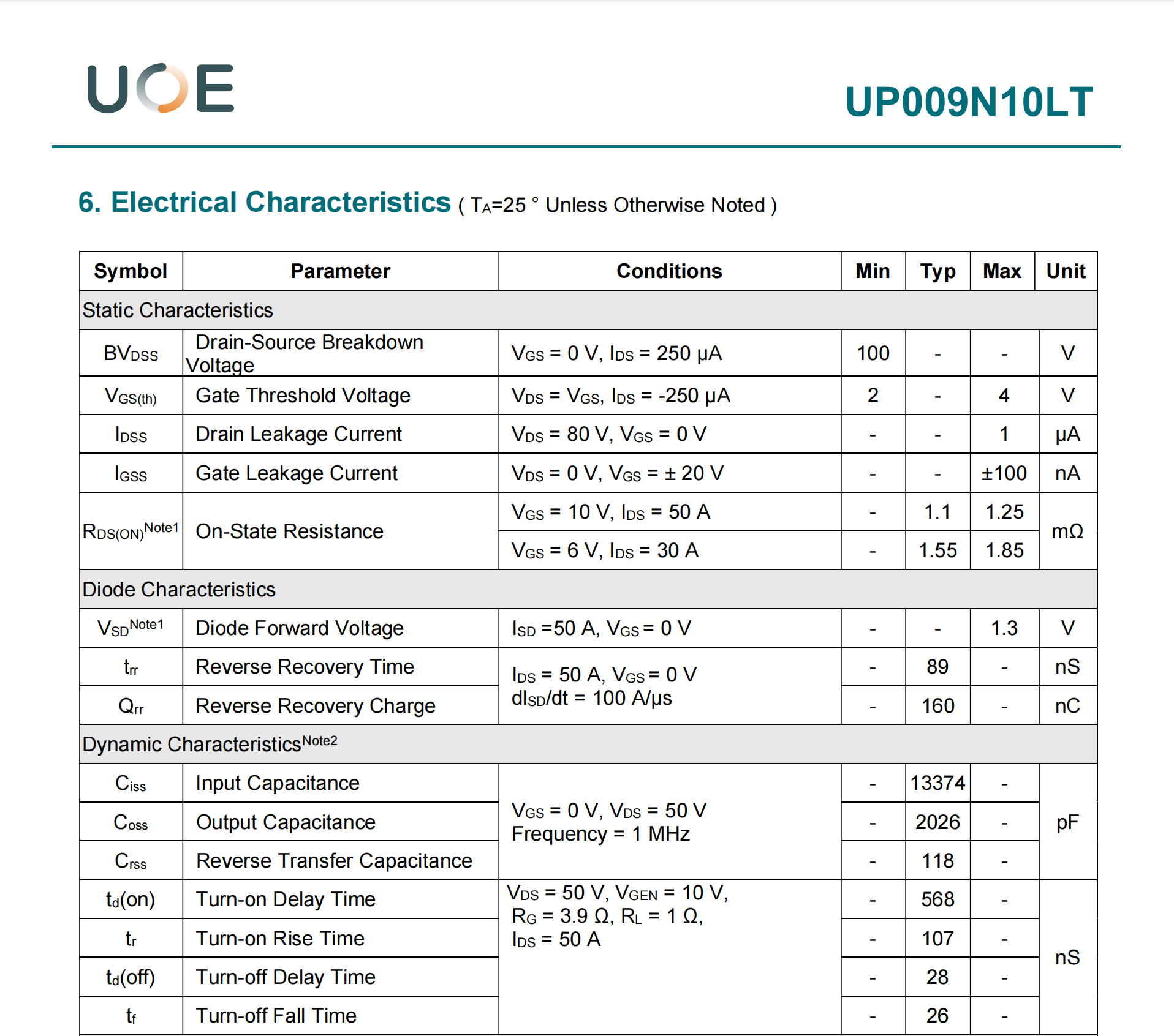
6. Electrical parameter
The MOSFETs in the TOLT package have the same RDS(on) value as the corresponding TOLL parts. For example, the excellent 100V MOSFETs in TOLT package (UP009N10LT) and the corresponding TOLL(UP009N10T), RDS(on),max are all 1.25 mΩ.
Compared to TOLL, the biggest improvement of TOLT at a normal 2s2p board with through-holes and an ambient temperature of 85°C was a significant reduction in the thermal resistance Rth to the junction to the heat sink. The Rth is reduced by nearly 50%, which results in a more than 90% increase in total dissipated power.
Sum up
The new top-cooling TOLT package is implemented on FR4 PCBS for high-power industrial applications. TOLT improves electrical performance by shortening the thermal path from the core junction to the heat sink, thereby improving thermal resistance.


